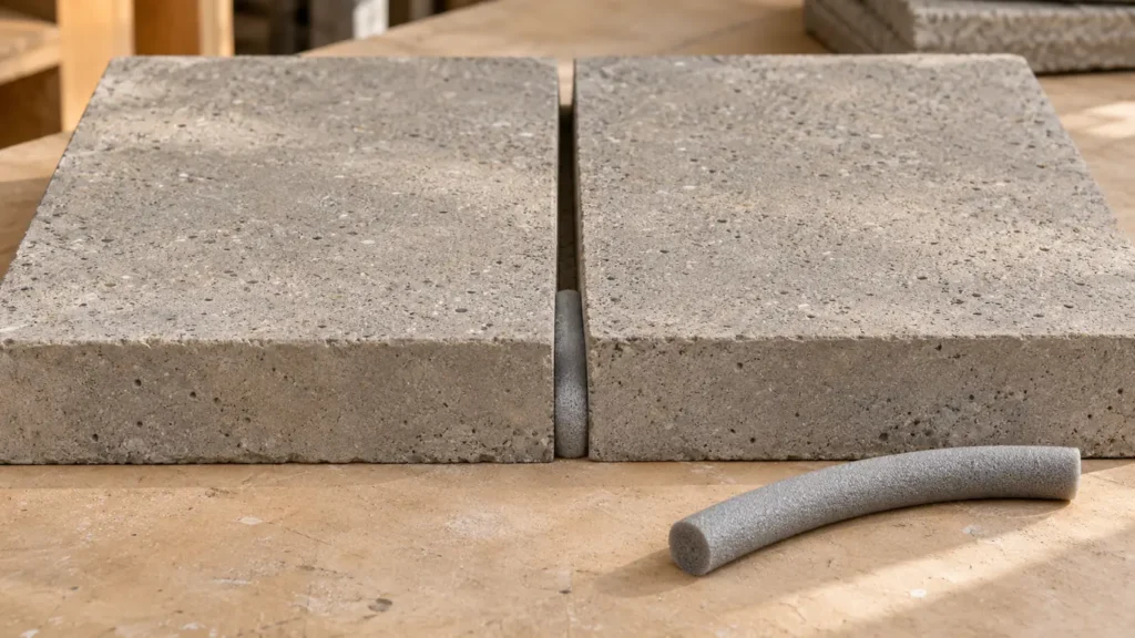
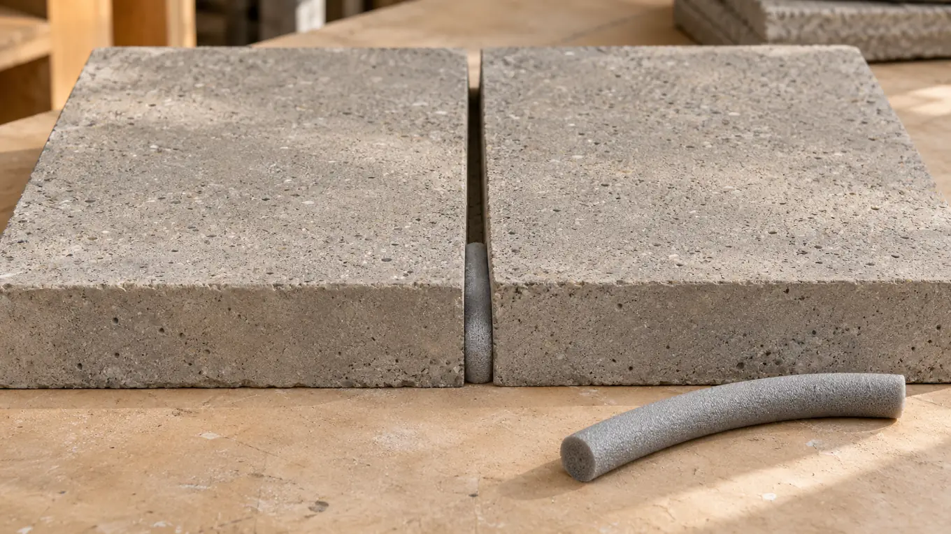
Backer rod is a compressible foam insert that sets the depth of a sealant bead and provides a surface the sealant can release from as the joint moves. In a typical moving joint, the sealant bonds to the two opposing sides. The backing supports the bead during application and helps keep it from bonding at the bottom. Choose the rod for the sealant, exposure and actual gap, then check how deep it sits before the crew covers it.
A tidy bead can conceal a surprising range of conditions. At one end of a joint, the rod may be firmly seated. A short distance away, a wider opening may let it drop as soon as the installer applies pressure. Both areas can look alike after tooling. A useful inspection therefore starts while the joint is still open, with a ruler, an approved detail and a record of which rod was installed at each change in width.
Table of Contents
1. Understand what backer rod does in a moving joint
As two adjoining surfaces move apart, the cured sealant stretches across the opening. When it bonds to both sides and also to the base, that third bond restrains the bead and can concentrate stress. The sealant may split internally or pull away from a side. Compatible backer rod separates the bead from the base and supports the intended cross-section. Its rounded face usually leaves more sealant near the sides and less through the center after the bead is tooled.
Check which surfaces the detail identifies for bonding. For a joint between a concrete panel and a metal frame, for example, they may be the prepared concrete and the finished metal surface. The specification also needs a sealant suited to the movement and the substrates. The wider question of where the building needs movement joints belongs to the structural and envelope design. See the guide to expansion joints in buildings for that design context.
2. Select the foam type for the sealant and exposure
Closed-cell foam has a skin and generally takes up little water, which can make it suitable for exposed joints where the sealant manufacturer approves it. Handle it carefully. Puncturing the surface can release gas into fresh sealant and leave bubbles. Open-cell foam is typically easier to compress into an uneven gap, but its interconnected cells can take up water. Check whether the specified sealant system permits it in the joint’s expected exposure, especially where water may stand.
Bi-cellular or hybrid products are another option. Ask for the exact product designation and confirm compatibility with the sealant. Foam color and roll size give little information about cell structure or water absorption. A manufacturer’s recommendation can also distinguish between an exposed vertical joint and a horizontal one receiving a flowable sealant. Where the specification references it, compare the proposed product with the applicable backing classification in ASTM C1330 for cylindrical sealant backing.
3. Measure the opening before choosing a diameter
Measure the joint width at several locations and at the level where the backer rod will sit. A surface bevel or a damaged corner can make the opening look wider at the face than it is inside. On an uneven concrete edge, include narrow spots, wide spots and transitions. Select a diameter that compresses enough to stay seated while remaining within the rod manufacturer’s limits. Use the specified sizing guidance for that particular material because different products compress differently.
A backer rod diameter that works for most of the run can be too loose at a panel corner and too tight at the next return. Test a short length at both extremes. Check whether light tooling pressure moves it and whether seating it would require excessive force. Where the measured widths fall into different acceptable ranges, record the rod sizes by joint segment. If the gap itself falls outside the design allowance, bring that variation to the designer before proceeding.
4. Set the bead depth from the finished sealant profile
The position of the backer rod comes from the required sealant thickness and the specified finish. If the joint is recessed, the distance from the wall face to the crown of the foam includes both the recess and the bead thickness at its center. A depth reading taken from the wall face needs to account for that offset. Check the approved profile so the installer and inspector measure from the same reference, particularly around chamfered or irregular edges.
For example, if the approved detail places the middle of the finished sealant surface 3 mm below the adjacent face and calls for 6 mm of sealant there, the top of the rod should sit about 9 mm below that reference. These dimensions describe the example. Use the joint design and product limits for the job in hand. For one example of how sizing, center depth and shallow-joint backing are specified together, see the Sikaflex TX 1 installation guidance.
5. Prepare the sidewalls and seat the rod consistently
During repair, remove loose old sealant and backing and prepare the bonding faces according to the new sealant system. Check the condition of the substrate before choosing a preparation method. Concrete laitance, release agents, incompatible old sealant and residue on coated metal can all affect adhesion. Confirm that any primer is suitable for the actual sidewall finish and that the installer knows the required order and timing of operations. Keep prepared surfaces clean while placing the backer rod.
Compress and seat the backer rod with a blunt tool or a roller set to the required depth. Stretching the foam along its length can change its diameter and leave a gap when it relaxes. Seat the ends snugly without overlapping, and check the depth again where lengths meet. If closed-cell foam is punctured or distorted during installation, address the affected section before applying sealant. Corners and offsets deserve a second check because they are easy places to create a dip.
6. Choose a compatible bond breaker for shallow joints
Some joints have a solid base close to the surface. There may be enough room for the specified bead but too little room to seat backer rod at the correct depth. A compatible bond breaker tape can separate the sealant from that base when the approved system permits it. The tape needs to lie flat and stay clear of the sidewalls that need to bond. Check the resulting profile against the required sealant depth before committing to the full run.
A tape is thin, so the existing base still determines the available depth. If the base varies or is too shallow for the sealant’s permitted geometry, the detail needs a design decision. Similarly, an open slot with no stable base needs backing capable of supporting the application. Compare these conditions at the first inspection and note them on the drawing. It is easier to agree on a revised detail before primer and sealant crews mobilize.
7. Check the first completed section before scaling up
Review a short installation that includes a straight run and a representative change in width or direction. Before sealing, confirm the material identification, the depth to the backer rod and the condition of both bonding faces. After application and tooling, look for continuous contact at the edges and the specified finish. An approved field adhesion check after the sealant cures can help assess the prepared substrates. Agree in advance on the method, acceptance criteria and repair of the test area.
Look at any defects alongside the records from before sealing. An isolated bubble over a section that was difficult to seat warrants a check of the foam and installation technique. A bead that separates along one side also warrants a check of substrate preparation and primer. The appearance can guide the investigation, while the sample and installation record make it easier to find the cause. See Aloda’s construction services for the types of work the company undertakes.
8. Record changes in the joint before the sealant hides them
A simple inspection record can identify where backer rod type, diameter or depth changes along the joint. Take representative photos with a scale at transitions and at any approved change in detail. Include the sealant designation and the substrates actually encountered. If a joint needs maintenance later, this record can help distinguish a local installation issue from a change in movement, drainage or the surrounding materials. If the crew finds a location that needs a second detail, attach its approved drawing so future repairs can reproduce the change.
When a section fails in service, inspect the failed bead before removing the whole run. Photograph whether it tore through the middle or released cleanly from one side, and note where the backer rod sits relative to nearby sections. That evidence helps determine whether a new bead can use the same geometry and preparation or whether the detail needs to change. To discuss a joint repair, contact Aloda with the measured opening, photographs and the existing detail if available.
Frequently Asked Questions
Can I use the same rod diameter throughout a joint?
Yes, if the actual joint widths all fall within the approved compression range for that diameter. Measure the widest and narrowest points, check the fit, and identify any locations that need a different size.
Does a deeper bead make a moving joint stronger?
A deeper bead changes the way it deforms. Use the joint profile and depth range for the selected sealant and movement conditions. Extra material can make it harder for the joint to move as intended.
Can I leave existing foam in place during repair?
Inspect its condition, depth and compatibility first. Replace loose, contaminated, damaged or unsuitable backing so the new bead can be installed to the approved profile.